
Plate width, edge heat loss, effective induction heating area and material positioning all affect transverse temperature uniformity
A common situation in continuous steel plate induction heating is:
The temperature measured at the center of the plate reaches the process target, while the two edges remain cooler.
If the infrared pyrometer measures only the centerline, the outlet temperature displayed by the control system may appear completely normal.
However, this does not necessarily mean:
The entire plate width has reached the required thermal condition.
For round bars and steel pipes, engineers often focus on temperature distribution through the section or wall thickness.
For wide steel plates, another important dimension must be considered:
Transverse temperature distribution—from one edge of the plate to the other.
Therefore, instead of asking only:
“What is the outlet temperature?”
a more useful engineering question is:
“Where is that temperature being measured?”
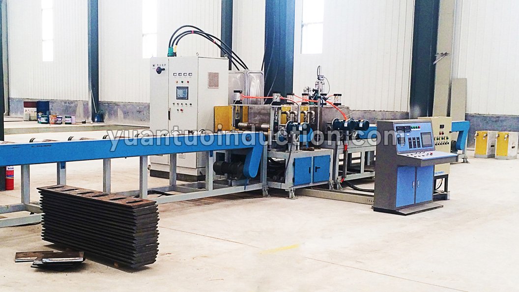
The center of a steel plate is surrounded by hot material, while the edges are directly exposed to the surrounding environment.
As a result, the thermal conditions at the edges differ from those in the center.
During continuous heating, this can create the following situation:
Heat Is Better Retained in the Center
↓
Edges Lose Heat More Rapidly
↓
A Transverse Temperature Difference Develops
As plate width increases, this issue becomes increasingly important to evaluate.
Therefore:
A transverse temperature difference does not automatically mean that the total induction power is insufficient.
The real issue may instead be:
Uneven energy distribution combined with different heat-loss conditions across the plate width.
For wide steel plates, inductor design cannot be based only on:
The design also needs to consider:
Electromagnetic coupling and the effective heating area across the entire plate width.
If the inductor does not properly match the plate geometry, the heating pattern may become uneven.
For example:
Therefore, the engineering evaluation should consider:
Plate Width + Plate Thickness + Material Grade + Target Temperature + Line Speed + Inductor Design
rather than determining the system from only:
Plate Thickness + Power
This is one reason why induction heating systems for wide steel plates often require a customized engineering design based on the actual product range.
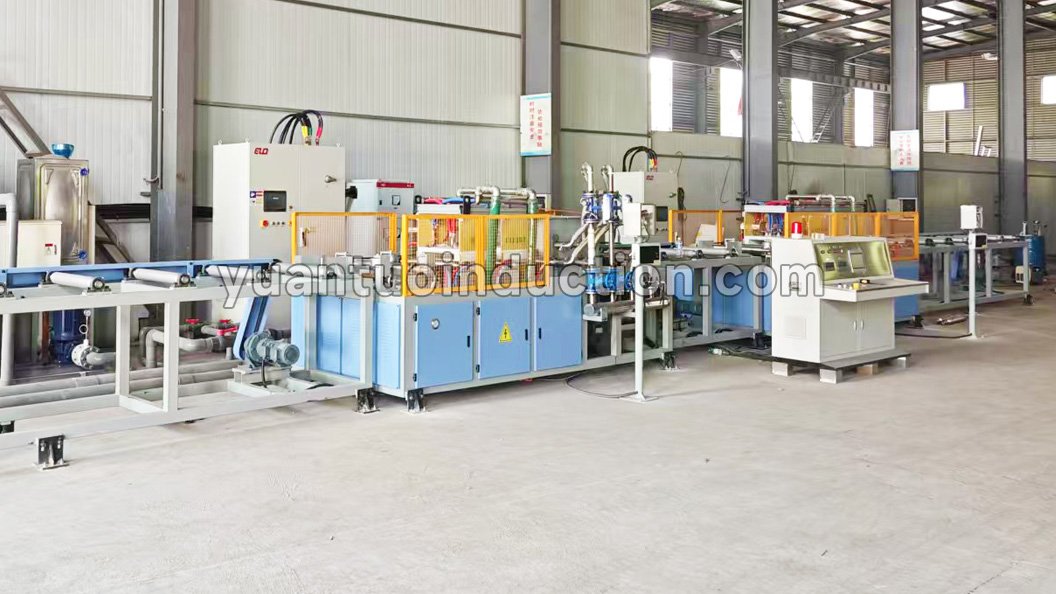
A common adjustment when the plate edges are too cool is:
“Increase the induction power.”
This may help if the entire plate is receiving insufficient heat.
However, if the main problem is the transverse distribution of energy, increasing total power alone may not solve it.
The result could be:
Higher Total Power
↓
Center Temperature Rises Faster
↓
Center Becomes Too Hot
↓
Edges Still Remain Below the Desired Temperature
In this case, the temperature distribution does not necessarily become more uniform.
Therefore, when cooler plate edges are detected, it is important to distinguish between three different conditions:
These conditions require different engineering adjustments.
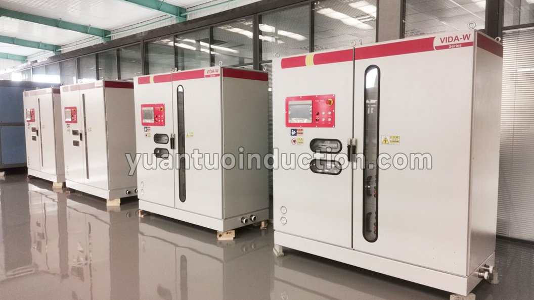
A steel plate heat treatment line may need to process more than one product size.
The same line may handle:
When plate width changes:
The relationship between the plate and the induction heating zone also changes.
A fixed process setting that works well for a narrower plate may not produce the same transverse temperature distribution on a wider plate.
For multi-size steel plate projects, it is therefore important to evaluate:
The design objective should not simply be:
“Can the widest plate physically pass through the system?”
A better question is:
“Can the main production sizes operate continuously and consistently within the required process window?”

Induction heating performance depends not only on electrical parameters but also on the position and movement of the workpiece.
If the plate experiences:
the electromagnetic coupling conditions on the two sides may change.
The result can be:
One side reaches the required temperature while the opposite side remains cooler.
A continuous steel plate heat treatment line therefore needs to consider mechanical systems such as:
In other words:
Mechanical conveying stability is also part of temperature control.
Suppose the outlet temperature measured at the plate center is within the required process range.
The control system may conclude:
“Heating condition is acceptable.”
But if:
a single centerline measurement cannot fully represent the thermal condition across the complete plate width.
For projects with strict temperature-uniformity requirements, the temperature measurement strategy should therefore be designed according to:
The objective is not simply:
“Install more pyrometers.”
The more important objective is:
“Make sure the temperature data represents the thermal condition that actually needs to be controlled.”
If the heated plate enters a spray quenching section, its thermal condition before quenching is critical.
Consider this situation:
Plate Center: Correct Austenitizing / Process Temperature
but:
Plate Edges: Lower Temperature
Even if the downstream spray cooling system operates consistently, the final plate may still show transverse variations in heat treatment results.
These may appear as differences in:
Therefore, when a quenched plate shows inconsistent properties across its width, the investigation should not focus only on:
Water flow or spray pressure.
It should also examine:
Whether the entire plate width had reached the required thermal condition before entering the quenching section.
This is an important principle in continuous heat treatment:
A downstream quality problem may originate from the upstream heating stage.
Internal Link: Steel Plate Quenching Line
When cooler edges are detected, increasing total power should not automatically be the first adjustment.
A more systematic troubleshooting sequence is:
Check:
↓
Confirm:
↓
Evaluate:
↓
Including:
↓
Evaluate:
The troubleshooting logic can therefore be summarized as:
Temperature Measurement
↓
Plate Position
↓
Inductor Matching
↓
Power / Frequency / Speed
↓
Final Heat Treatment Result
A complete steel plate heat treatment solution should not be designed around only one question:
“What temperature does the plate need to reach?”
Instead, the complete process should be evaluated:
Plate Width + Thickness + Length + Material Grade
↓
Target Temperature + Uniformity Requirement
↓
Induction Frequency + Power + Effective Heating Area
↓
Conveying + Guiding + Centering
↓
Online Temperature Measurement
↓
Quenching / Cooling
↓
Final Properties
For a customized steel plate project:
Temperature uniformity is the combined result of inductor design, power distribution, conveying stability, temperature measurement and downstream process matching.
It is not determined by one parameter alone.
| Parameter | Recommended Information |
|---|---|
| Plate Width | Minimum, maximum and main production sizes |
| Plate Thickness | Main thickness range |
| Plate Length | Minimum, maximum and typical length |
| Material Grade | Steel grade |
| Heat Treatment Process | Heating, quenching, tempering, etc. |
| Target Temperature | Required heating outlet temperature |
| Temperature Uniformity | Transverse and/or longitudinal requirement |
| Production Capacity | t/h, pcs/h or production takt |
| Conveying Method | Continuous or other operating mode |
| Final Properties | Hardness, microstructure or mechanical properties |
If an existing quenching system is already installed and only the upstream induction heating section is required, it is also useful to provide:
Quenching Line Entry Speed + Main Plate Sizes + Required Entry Temperature + Temperature Uniformity Requirement
This allows the induction heating section to be matched to the actual downstream production takt.
Not necessarily. The cause may also be edge heat loss, effective inductor heating width, transverse energy distribution or plate positioning.
It may help when total heat input is insufficient. However, if the main issue is uneven transverse energy distribution, increasing total power may raise the center temperature further without fully correcting the cooler edges.
As plate width increases, transverse energy distribution, edge heat loss, plate centering and temperature measurement become more important. Therefore, the engineering design generally requires more attention to these factors.
Because the plate position relative to the effective induction heating zone changes. This can create different electromagnetic coupling conditions on the two sides of the plate and affect transverse temperature distribution.
The spray system should be checked, but cooling is not the only possible cause. The heating condition before quenching should also be verified to confirm that the edges reached the required process temperature.
For a wide steel plate induction heating project, plate thickness alone is not enough to define the system.
A technical evaluation should consider:
Plate Width + Thickness + Length + Material Grade + Target Temperature + Temperature Uniformity + Production Capacity + Quenching Requirements
Hebei Yuantuo Electromechanical develops customized complete-line solutions by coordinating:
Induction Heating + Effective Heating Area + Plate Conveying and Centering + Online Temperature Measurement + Quenching/Cooling + Line Control
according to the actual workpiece range and production process.
If an existing steel plate quenching line is already installed and an upstream induction heating section needs to be added or upgraded, please provide:
Plate Size / Material Grade / Inlet Temperature / Target Temperature / Line Speed / Temperature Uniformity Requirement
for an initial engineering evaluation.
WhatsApp:+86 15226757228
Email:yuantuo38@gmail.com
Website:www.yuantuoinduction.com
